
It is very conceptual and essential to understand. If the radiating structure happens to have impedance around 377Ω then depending on the geometry a plane wave can be generated in the near field.

2001 Q 1 Three Inductive Coils Each With A Resistance Of 15 Ohms
Answered Find The Average Power Absorbed By Each Bartleby

Electrical Engineering Ch 12 Ac Power 10 Of 38 What Is Average Power Supplied And Absorbed 26 5 Youtube
The voltage developed across an inductor as a result of current flow through it is given by the.
Power absorbed by inductor formula that have impedance. Thus the average power consumed by the circuit will be the instantaneous power within one cycle. Which of these precautions should be taken when installing devices for lightning protection in a coaxial cable feed line. Power triangle for series RL circuit is shown below The electrical power factor cosθ is defined as ratio of the true power to apparent power.
In electronics impedance matching is the practice of designing the input impedance of an electrical load or the output impedance of its corresponding signal source to maximize the power transfer or minimize signal reflection from the load. You have to use the formula p VI cos Ø phase value between p and I is 90. Average Power Formula.
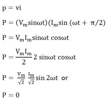
The next level of switchgear is used for industries that do not have mission critical power requirements. This power of course is equal to that delivered to Z since the inductor absorbs no. Alternative words used for Real Power Actual Power True Power Watt-full Power Useful Power Real Power and Active Power and denoted by P and measured in units of Watts W ie.
A source of electric power such as a generator amplifier or radio transmitter has a source impedance equivalent to an electrical resistance in series with. When a purely resistive load of value equal to surge impedance is connected at the receiving end of the line then the reactive power generated by the shunt capacitor will be completely absorbed by the series inductor of the transmission line. Thus for a peak current of 40 kA the voltage of the pulse can be as high as.
Although slotted lines used to be the principal way of measuring unknown impedance at microwave frequencies they have largely been superseded by the modern network analyzer in terms of accuracy versatility and convenience. As was mentioned before the angle of this power triangle graphically indicates the ratio between the amount of dissipated or consumed power and the amount of absorbedreturned power. What is Active Power.
The average power absorbed by the circuit becomes the sum of power stored and returned through complete one cycle. Academiaedu is a platform for academics to share research papers. A 200-m tall hollow aluminum flagpole is equivalent in line and is therefore subjected to more shear force than poles stiffness to a solid cylinder 400 cm in diameter.
Is the input impedance of the device then for beginmatrix vV_mcosomega tphi. If the potential difference across C R are 120 V 90 V respectively and if the rms. The town gets power from the line through a 4000-220 V step-down transformer at a sub-station in the town.
Variation of Impedance and Phase Angle with Frequency. The resistance of the two wire line carrying power is 05 Ω per km. This is in contrast to an ordinary resistor in which an increase of applied voltage causes a proportional increase in current due to Ohms law resulting in a positive resistance.
So total power in series RL circuit is given by adding the power dissipated by the resistor and the power absorbed by the inductor. We appreciate that you have chosen our cheap essay service and will provide you with high-quality and low-cost custom essays research papers term papers speeches book reports and other academic assignments for sale. If the standing wave ratio for a transmission line is 14 then the reflection coefficient for the line is.
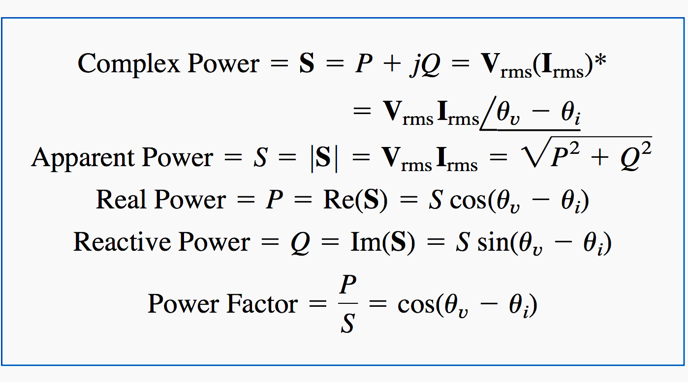
Include a parallel bypass switch for each protector so that it can be switched out of the circuit when running high power B. When expressed as a fraction this ratio between true power and apparent power is called the power factor for this. For establishing the expression of complex power we have to first consider a single phase network thats voltage and current can be represented in complex form as Ve jα and Ie jβWhere α and β are angles that voltage vector and current vector subtend with respect to some reference axis respectively.
In electronics negative resistance NR is a property of some electrical circuits and devices in which an increase in voltage across the devices terminals results in a decrease in electric current through it. A strong wind in straight parts of the line. Impedance in an AC system is still measured in ohms and represented by the equation Z VI but V and I are frequency-dependent.
NCERT solutions of chapter 7 physics class 12. If they are out of sync some of the power flowing through the circuit cannot be absorbed by connected devices resulting in a loss of efficiency. Impedance matching is designing source and load impedances to minimize signal reflection or maximize power transfer.
Many low impedance connections between the PE conductors and the grounding electrodes combined with multiple-impedance paths between the electrodes and the impedance on conductors create a complex grounding system with an impedance network see figure 7 b and the currents that flow through it cause different grounding potentials on the the network interconnections. Question 725 A small town with a demand of 800 kW of electric power at 220 V is situated 15 km away from an electric plant generating power at 440 V. All the power fed into it.
If the series RLC circuit is driven by a variable frequency at a constant voltage then the magnitude of the current I is proportional to the impedance Z therefore at resonance the power absorbed by the circuit must be at its maximum value as P I 2 Z. P Active Power is the actual power which is really transferred to the load such as transformer induction motors generators etc and dissipated in the circuit. Average Power Formula Instantaneous Power Formula.
Current of the circuit is 3 A calculate the i impedanceii power factor of the circuit. It also happens to be the same angle as that of the circuits impedance in polar form. The above quantity has a dimension of resistance is known as the Surge impedance of the line.
As the current flowing through the circuit and voltage are dependent on time the instantaneous power is also dependent on time t. The region around λ2π. The range of this impedance is between 300 Ohms and 1000Ohms.
In question number 5 students have to find the net power absorbed by each circuit over a complete cycle where RMS value of I or current is 1592 A and RMS value of voltage is 220 volts. Enter the email address you signed up with and well email you a reset link. Power converter design aims at improving the efficiency.
We even have an urgent delivery option for short essays term papers or research papers needed within 8 to 24 hours. Include a series switch in the ground line of each protector to prevent RF overload from inadvertently damaging the protector. The pole in Figure 524 is at a 900º bend in a power 34.
Z C is the characteristic impedance also referred to as surge impedance seen by the pulse in the direction of travel. A capacitor and a resistor are connected in series with an ac.

What Is Maximum Average Power Transfer Formula In Ac Circuits Wira Electrical
Chapter 7 Ac Power Analysis Ppt Video Online Download
Do Inductor Or Capacitor Consume Any Power Quora

Power Absorbed In An Inductor In An Rl Circuit During Step Response Electrical Engineering Stack Exchange

Electrical Power In Ac Circuits And Reactive Power
What Is The Complex Power And How It Figures In Power Analysis Eep
Ac Power Analysis Instantaneous Average Power Ppt Download
What Is A Pure Inductive Circuit Phasor Diagram Waveform Circuit Globe


